B31DD Mini-Project Report
Traffic Light Display System with Servo Control and Serial Monitoring
1. Project Introduction
The Traffic Light Display System is an embedded project designed to simulate a real-world traffic light controller using an AVR microcontroller. This system manages traffic flow by controlling red, yellow, and green LEDs, incorporates a servo motor to represent mechanical signaling (e.g., pedestrian crossing), displays countdown timers on an LCD, and logs traffic light changes via serial communication. Additionally, it features an interrupt-driven button allowing pedestrians to request crossing, thereby altering the normal traffic sequence.
Key Techniques Used:
- Input/Output
- Timer
- Interrupt
- PWM and Servo Control
- Serial Communication
- LCD Display
2. Functionalities
- Traffic Light Control: Manages red, yellow, and green LEDs to simulate traffic signals.
- Servo Motor Integration: Adjusts the servo position based on the active traffic light (0° for red, 90° for green).
- LCD Display: Shows the current traffic light status and a countdown timer.
- Serial Communication: Logs traffic light changes to a serial monitor for monitoring and debugging.
- Interrupt-Driven Pedestrian Button: Allows pedestrians to request crossing, triggering a modified traffic sequence.
3. Hardware Components and Schematics
3.1 Components Used
- Microcontroller: AVR (e.g., ATmega328P)
- LEDs: Red, Yellow, Green
- Servo Motor: Standard hobby servo
- LCD Display: 16x2 character LCD
- Button: Momentary push-button
- Resistors: Current-limiting resistors for LEDs
- Power Supply: 5V regulated supply
- Miscellaneous: Breadboard, jumper wires, USB-to-Serial adapter

3.2 Connection Overview
- LEDs:
- Red LED: Connected to PORTB3 through a current-limiting resistor.
- Yellow LED: Connected to PORTB4 through a current-limiting resistor.
- Green LED: Connected to PORTB5 through a current-limiting resistor.
- Servo Motor:
- Control Pin: Connected to PORTB2 (OC1B).
- Power: Connected to an external 5V supply with a common ground.
- LCD Display:
- Data Lines (D4-D7): Connected to PORTD4-PORTD7.
- Control Lines (RS, EN): Connected to PORTB0 and PORTB1.
- Button:
- One Terminal: Connected to PORTD3.
- Other Terminal: Connected to GND with an internal pull-up resistor enabled.
- Serial Communication:
- TX Pin (PD1): Connected to RX of USB-to-Serial adapter.
- Common Ground: Ensured between microcontroller and adapter.
4. Techniques and Methodologies
4.1 LED Control
- Utilized PORTB pins to control red, yellow, and green LEDs.
- Employed bitwise operations to set and clear specific LED states without affecting others.
4.2 Servo Motor Control
- Implemented PWM (Pulse Width Modulation) using Timer1 in Fast PWM mode.
- Mapped specific angles (0° and 90°) to corresponding pulse widths to position the servo accurately.
- Configured the servo to reset to 0° during red light and move to 90° during green light.
4.3 LCD Display
- Initialized the LCD in 4-bit mode for efficient data transmission.
- Displayed the current traffic light status and a countdown timer on two lines.
- Utilized
sprintffor formatting countdown strings.
4.4 Serial Communication
- Configured USART for serial communication at 9600 baud rate.
- Implemented functions to initialize USART, transmit single characters, and send strings.
- Logged every traffic light change with appropriate messages for monitoring.
4.5 Interrupt Handling
- Configured an external interrupt (INT1) on PORTD3 to detect button presses.
- Employed a sequence in the ISR, when the button is pressed, to display the yellow light for 3 seconds and then the green light for 5 seconds for pedestrians crossing the road.
5. Demo Results
5.1 Normal Traffic Sequence
-
Red Light:
- LED: Red LED on.
- Servo: Positioned at 0°.
- LCD: Displays “RED LIGHT” with an 8-second countdown.
- Serial: Logs “RED LIGHT”.

-
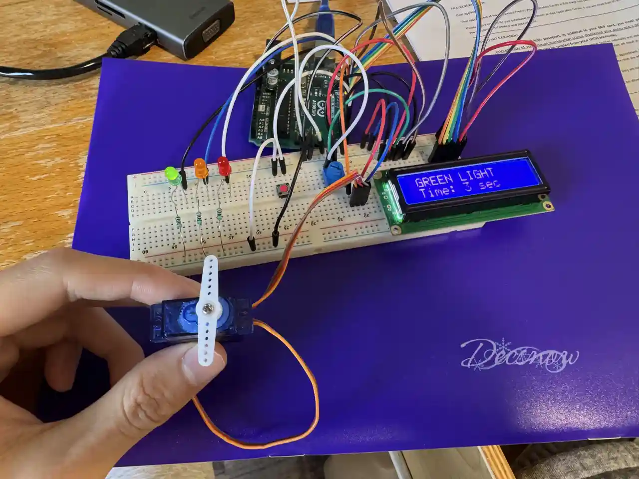
Green Light:
- LED: Green LED on.
- Servo: Positioned at 90°.
- LCD: Displays “GREEN LIGHT” with a 4-second countdown.
- Serial: Logs “GREEN LIGHT”.

-
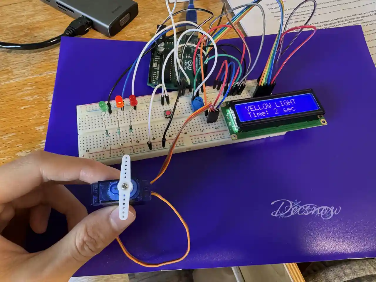
Yellow Light:
- LED: Yellow LED on.
- LCD: Displays “YELLOW LIGHT” with a 2-second countdown.
- Serial: Logs “YELLOW LIGHT”.
(Repeat cycle)

5.2 Pedestrian Request Sequence
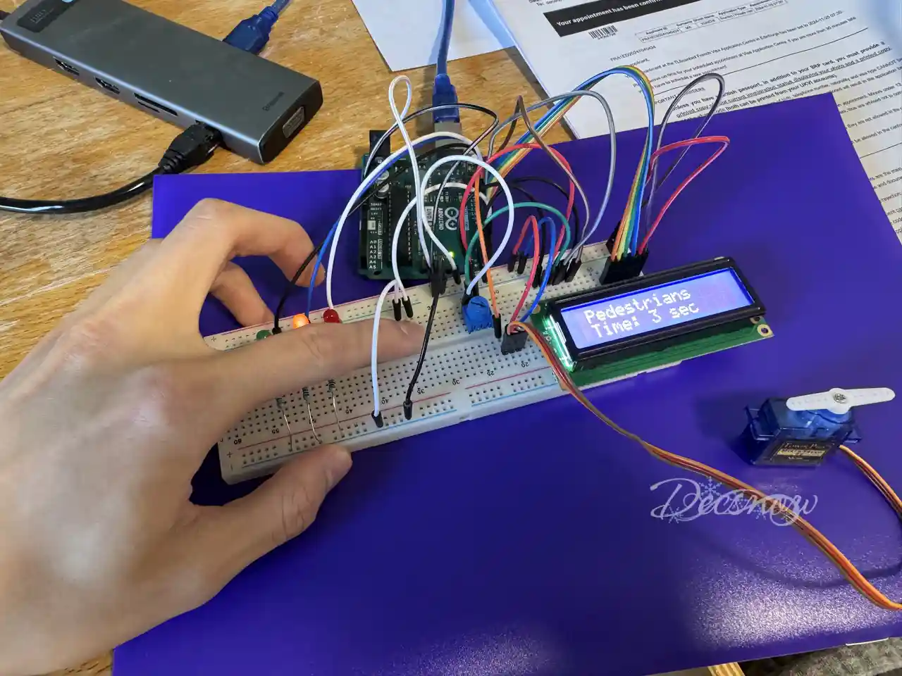
- Button Press Detected: Triggers the ISR to execute the special sequence.

-
Yellow Light:
- LED: Yellow LED on.
- LCD: Displays “Pedestrians” with a 3-second countdown.
- Serial: Logs “YELLOW LIGHT”.
-
Green Light:
- LED: Green LED on.
- Servo: Positioned at 90°.
- LCD: Displays “GREEN LIGHT” with a 5-second countdown.
- Serial: Logs “GREEN LIGHT”.
-
Return to Normal Sequence:
- Servo: Resets to 0°.
- Resumes Normal Traffic Cycle.
6. Performance Evaluation
- Timing Accuracy:
_delay_ms()provided sufficient timing for demonstration purposes, but hardware timers are recommended for higher precision. - Interrupt Responsiveness: The system detected button presses and executed pedestrian requests promptly.
- Servo Control: Smooth and accurate transitions between designated angles.
- Serial Logging: Reliable logging of traffic light changes for monitoring.
- LCD Display: Consistently displayed accurate statuses and countdowns.
Areas for Improvement:
- Implement software or hardware debouncing for the button.
- Extend servo angle functionality for versatile signaling.
- Replace
_delay_ms()with timer-based delays for concurrent tasks. - Add error handling for USART transmission and routine interruptions.
7. Conclusion
The Traffic Light Display System integrates various embedded system components controlled by an AVR microcontroller. Interrupt-driven button handling adds interactivity and realism, showcasing practical applications of PWM, serial communication, and user interfaces.
8. References
- AVR Microcontroller Datasheet
- Arduino Documentation
- LCD Display Lab3 Tutorials
- Servo Motor Control course material
- Serial Communication course material


